 PACS
Desktop Viewer
 PACS
Desktop Viewer
The mammography plug-in module includes a collection of features, tools, and hanging protocols dedicated to the display and handling of mammography studies. They include skin line detection, displaying CAD overlays, mammography-specific hanging protocols and built-in grid layouts, image positioning tools and support for optional image processing algorithms.
The mammography plug-in module requires an eRAD PACS Mammography plug-in module license. When the Viewer launches for the first time, if a valid license exists on the server and the user account is configured to use the plug-in module, the mammography module features are activated. The mammography plug-in module requires the workstation environment specified for an eRAD PACS diagnostic workstation plus FDA-cleared mammography monitors.
If reading breast tomography studies, the following enhancements are strongly recommended:
Processor speed: greater than 2GHz
RAM: minimum is twice the size of a breast tomography study
Disk space (Viewer cache): minimum is three times the size of all breast tomography studies read from the workstation in one day

Mammography Tools
The Mammography toolbar provides access to the breast imaging tools that are part of the mammography plug-in module.
| Icon | Function | Menu Item | Description |
|
Show CAD | Tools Mammo Mammo Show CAD Show CAD |
Show/hide mammography CAD markers |
|
Fit to breast |
Tools Mammo Mammo Fit to breast Fit to breast |
Magnify the image so the breast is maximally displayed to the shorter edge of the image frame. |
|
Snap to anatomy |
Tools Mammo Mammo Snap breast Snap breast <selected
area> <selected
area> |
Render the selected image at full resolution with the first detected part of the breast positioned in the selected area respectively justified in the image frame. |
|
Enhanced ROI |
Tools Mammo Mammo Enhanced ROI Enhanced ROI |
Activate a floating panel containing the AIE enhanced image data of the image behind it. Requires an AIE enhanced image exist in the thumbnail panel |
|
Invert breast image |
Tools Mammo Mammo Invert breast image Invert breast image |
Invert the window/level settings of breast image data, leaving the remaining data unchanged. |
|
Show skin line |
Tools Mammo Mammo Show skin line Show skin line |
Show/Hide the skin line. |
Skin Line Detection
The skin line detection tool outlines the breast skin line in mammography images. To show or hide the skin line of the selected image click the Show Skin Line icon from the mammography toolbar. When calculated, an icon appears in the top left corner of the image frame indicating processing is incomplete. If skin line detection fails, the icon turns into a warning icon. Place the mouse over the warning icon to display the message indicating the skin line could not be calculated.
Anatomical Greyscale Inversion
The anatomical greyscale inversion tool inverts the window and level settings for the breast image only leaving the remaining area uchanged. To invert the greyscale slope of the selected breast image, click the Invert W/L on Anatomy icon from the mammography toolbar. To identify the breast data, the tool requires successful generation of the skin line. If the skin line could not be calculated, a warning pops up and there is no change to the window/level settings.
Snap-To Image and Anatomy
The snap-to functions sets the image resolution to full (1:1) and reorients the image in the image frame as directed by the user.
There are two Snap-To icons available:
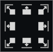
Both of these functions pop up a selection grid consisting of eight regions:

Select the region and the tool will display that portion of the image justified to the respective borders. Built-in accelerator keys and shortcuts exist for snapping to specific regions of the selected image both of which are available on the Tools/Mammo menu.
| Function | Menu Item | Hot Key | Description |
| Snap to next quadrant | Tools Mammography Mammography Snap progression Snap progression Next
quadrant Next
quadrant |
Ctrl+Alt+{ | Snap to the next quadrant (left to right, top to bottom). If no snap-to quadrant is applied, snap to the top left quadrant. Uses the snap-to-anatomy tool. |
| Snap to previous quadrant | Tools Mammography Mammography Snap progression Snap progression Previous
quadrant Previous
quadrant |
Ctrl+Shift+Alt+{ |
Snap to the previous quadrant (right to left, bottom to top). If no snap-to quadrant is applied, snap to the top left quadrant. Uses the snap-to-anatomy tool. |
| Snap to next segment | Tools Mammography Mammography Snap progression Snap progression Next
segment Next
segment |
Ctrl+Alt+} |
Snap to the next of the nine defined segments used in the snap-to-anatomy toolbar. The first instance snaps to the top left segment. |
| Snap to previous segment | Tools Mammography Mammography Snap progression Snap progression Previous
segment Previous
segment |
Ctrl+Shift+Alt+} |
Snap to the previous of the nine defined segments used in the snap-to-anatomy toolbar. The first instance snaps to the top left segment |
Progression Mode
The progression tool is similar to the snap-to tools with the additional feature that it splits the image into equal size segments such that each pixel exists in a single segment. The user can then progress through each segment, thereby displayed the full image without any duplication of data. They are available in the Tools/Mammo menu. Built-in accelerator keys exist for advancing to the next and previous segments.
| Function | Menu Item | Hot Key | Description |
| Advance to next view | Tools Mammography Mammography View progression View progression Next
view Next
view |
Shift+Ctrl+Alt+. |
Advance to the next view (left to right, top to bottom). Initial position is the top left view |
| Advance to previous view | Tools Mammography Mammography View progression View progression Previous
view Previous
view |
Shift+Ctrl+Alt+, | Advance to the previous quadrant (right to left, bottom to top) |
| Exit progression | Tools Mammography Mammography View progression View progression Exit
progression Exit
progression |
Shift+Ctrl+Alt+Del | Exit progression mode and restore the image to its original settings |
When in progression mode, the progression mode icon ? appears in the top left corner of the image frame.
Progression mode remains active until:
The user advances past the last segment
Exits using the menu option
Loads an image into the image frame
A border appears around the unique data in each segment which has a size that can be configured. The data displayed behind the border is data from the neighboring segment.
To change the size of the border:
If skin line was applied to the image during the viewer session, the progression mode segmentation is based on the anatomical structure. If skin line was never applied, the segmentation is performed on the entire image.
Note: When progression mode is active in an image frame, cine playback is disabled.
Fit To Anatomy Mode
Apply a calculated zoom factor to the selected image such that the anatomical structure in the image (the breast) is displayed as large as possible within the defined image frame. When applied, the anatomical structure will appear up to the edge of the image frame for the short of the two dimensions (width or height).
Note: This feature requires skin line detection to find the anatomical structure and will apply to the fit-to-image zoom factor if the skin line detection is unavailable or fails.
Enhanced ROI
The enhanced ROI tool displays the AIE enhanced images in a panel that floats over a defined region of the original image. The enhanced ROI tool requires both a mammography plug-in module license and an AIE Image Enhancement plug-in module license. It also requires the presence of an AIE enhanced image in the thumbnail panel. See details for manual and automatic generation of AIE enhanced images in the AIE Image Enhancement module section.
To activate the Enhanced ROI panel:
The default magnification factor is defined by the Enhanced ROI Zoom Factor defined in the Settings panel.

A CAD marker provides computer-aided diagnosis to mammography images.
The Viewer supports the CAD objects from the following manufacturers and systems:
CAD Overlays
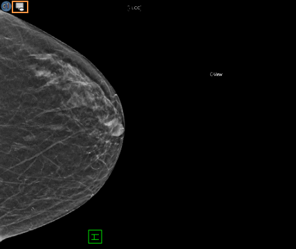
If a study includes a CAD marker, the presentation state icon (highlighted) appears in the top left corner of the image when it is displayed in an image frame.

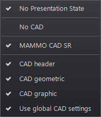
Selecting the presentation state icon reveals a dropdown menu consisting of current presentation state functions (show or hide):

When applied, these functions override the current CAD marker display state applied to each individual image using the image frame’s presentation state tool. When mammography CAD graphic and geometric overlays exist for an image, apply any of the options to just one image by selecting the applicable option from the list.
| Function | Description |
| CAD header | Heading on image indicating supported manufacturers and systems |
| CAD graphic | CAD marker header and only graphic overlays appear on each image. Available when both graphic and geometric overlays exist |
| CAD geometric | CAD marker header and only geometric overlays appear on each image. Available when both graphic and geometric overlays exist |
The default CAD overlay settings can be configured from the Tools/Mammo menu under Mammography CAD.

Mammography-Specific Layouts and Hanging Protocols
Mammography image review makes use of image layouts that differ from other study types and can be created using the hanging protocol tools. Those that cannot are included by default.
Built-in mammography-specific hanging protocols:
| Hanging Protocol | Description |
| ~ MG Comparison | Two monitor, four-up layout in which the bottom four frames are populated with, in order, the RCC, LCC, RMLO and LMLO images of the primary study, and the top four frames are populated with the same view of the first prior study. Use the Load Next/Previous Prior tool to quickly scroll through all loaded prior studies. |
| ~ MG Screening Protocol | Series of multiple views used to display a current mammography exam and one or more prior exams. |
| ~ MG Implant Default | Series of multiple views used to display a current mammography exam consisting of images showing breast implants. |
These hanging protocols are available when the Modality value of the primary study is MG. The HP requires the series description contain the strings RCC, LCC, RMLO and LMLO. Additional layout tools exist for creating mammography-specific hanging protocols.
See: Image Stacks